Capture the real thing.
3D scanning to bring existing shapes into a digital workflow, with the dimensions and reference features that matter to your project.
3D SCANNING PRECISION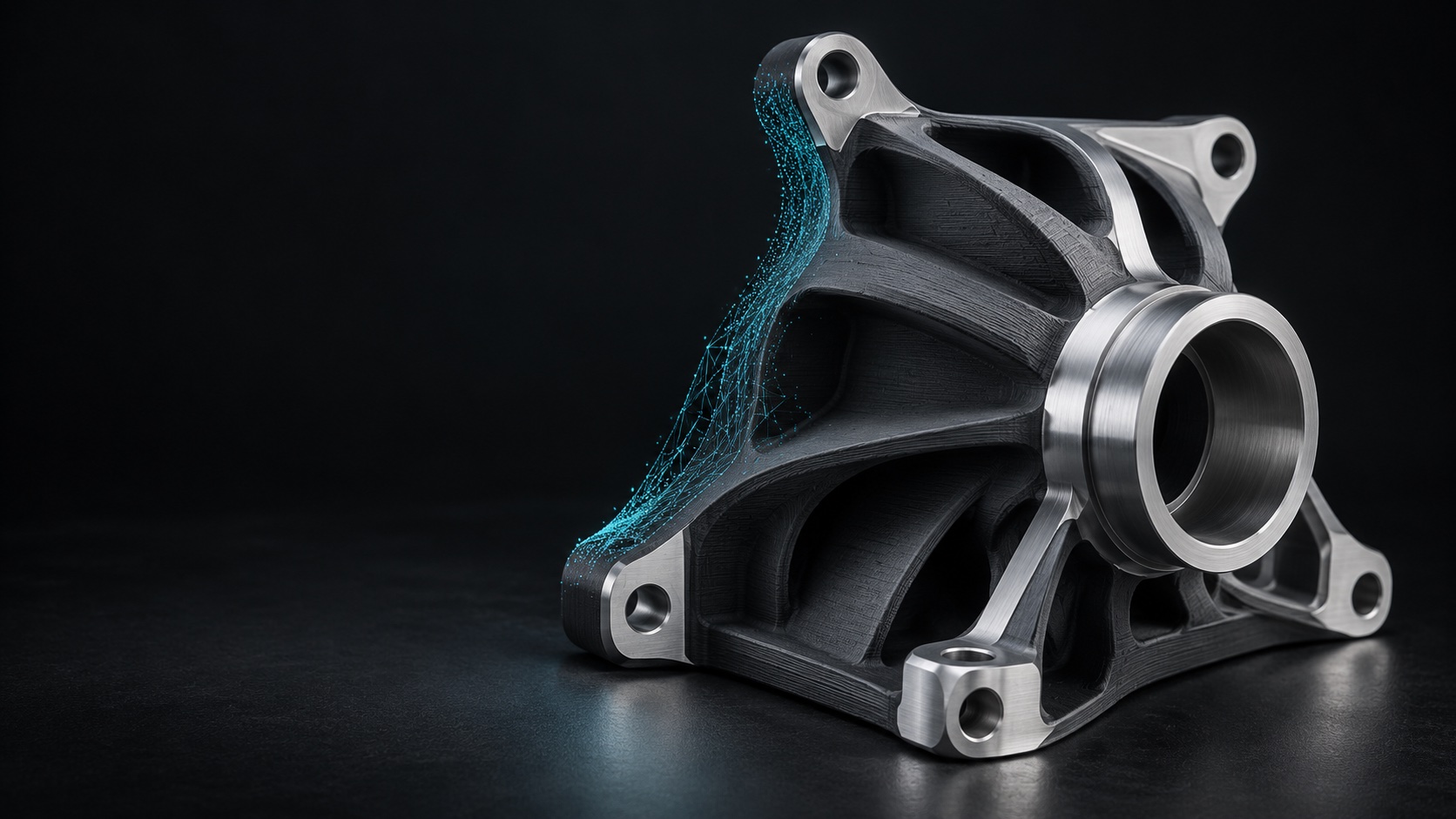
SCAN. DESIGN. MAKE.
A part to recreate. An idea to work through.
A better way to make it real.
01 / CAPABILITIES
Start with what you have—a physical object, a model, or a rough idea. We’ll work out the next practical step.
3D scanning to bring existing shapes into a digital workflow, with the dimensions and reference features that matter to your project.
3D SCANNINGCAD work for practical parts, mounting interfaces, and prototypes. Design decisions start with how the finished piece needs to work.
CAD & REVERSE ENGINEERING3D printing for prototypes, useful workshop parts, and creative builds. Make a first version, check the fit, and refine the details.
3D PRINTING02 / THE WORKSHOP
Precision Form 3D is a hands-on workshop for useful parts, creative builds, and the tools that connect them.
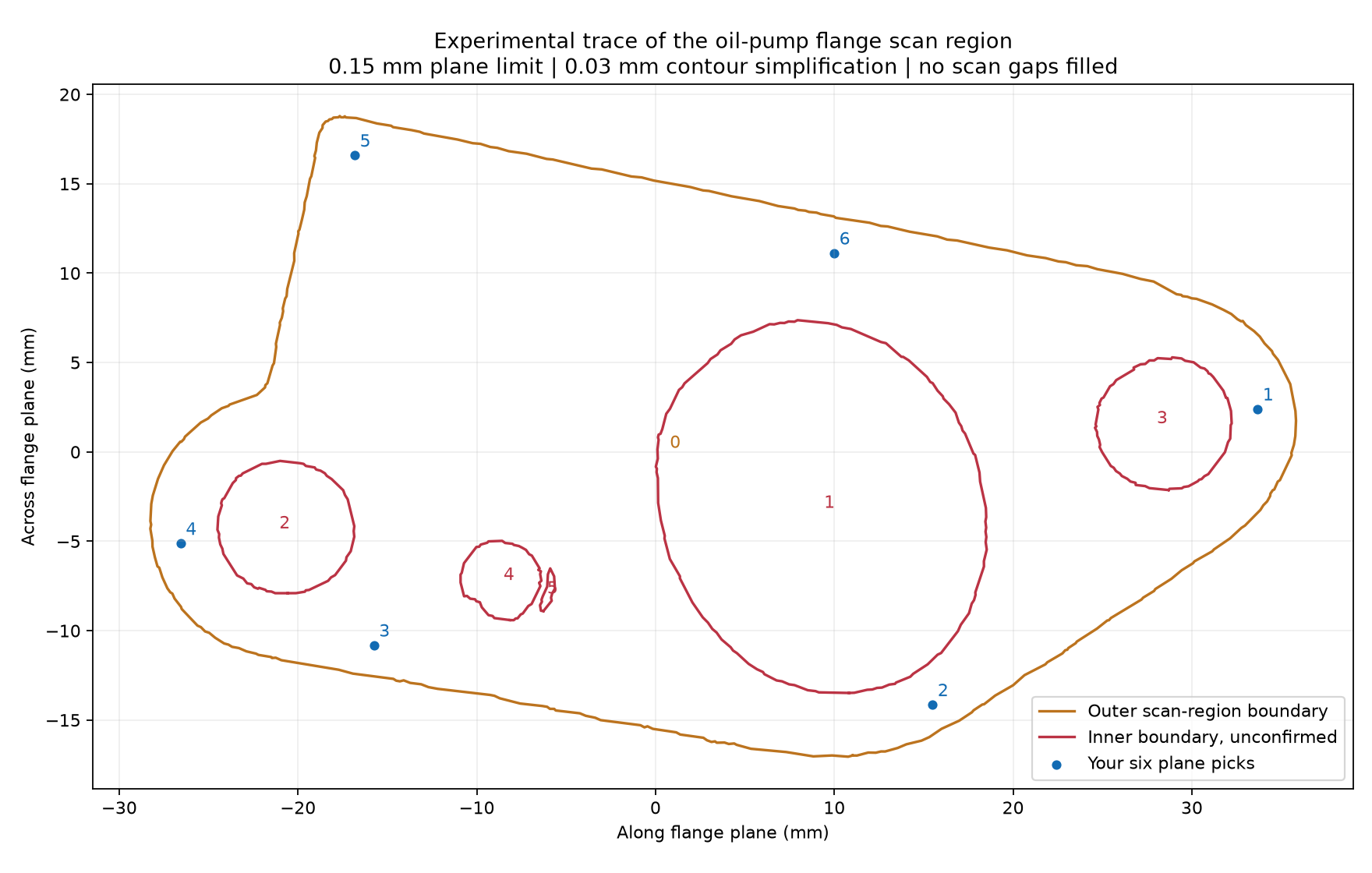
A real casting is the starting point for a scan-to-CAD study: locate mounting features, review the flange perimeter, and preserve the relationship between the scan and fitted geometry.
THE WAY WE WORK
Does it fit?
Does it align?
Does it work?
Those questions guide the process—from the first measurement to a prototype you can hold.
Useful geometry, sensible material choices, and real-world checks make the difference.
03 / BUILDING THE TOOLS, TOO
Our own Precision Form 3D application is taking shape alongside the physical work. It brings selected scan features into a practical CAD workflow, with you in control of what gets kept.
Inspect an STL scan and select the planes, origins, and mounting features that give the part context.
Fit selected curved regions and trace planar boundaries. Inspect the measurements before keeping a feature.
Export selected fitted geometry in STEP and the complete aligned scan in STL, in a shared coordinate frame.
Currently an early development prototype. Whole-part reconstruction and release packaging are still being developed and validated.
Ask about the softwareFROM FIRST IDEA TO FIRST PART
A clear goal and one useful first version are a good place to begin.
Share the object, sketch, model, or problem. What does it connect to? What needs to fit?
Choose a focused scan, design task, or print that answers the most useful question.
Review the geometry, test the prototype, and use what you learn to guide the next version.
04 / START A CONVERSATION
A part you want to recreate. A prototype you want to print. An idea that needs a little structure.
hello@pform3d.comPhotos, rough dimensions, and a description of how the part will be used help us get started.